Draw activity areas
Drawing an activity area is the most direct way to model new work in XECUTE. Use this method when you need full control over the shape, size, and location of the area, such as when grade control data isn’t available or you’re responding to operational changes.
Before you draw an activity area, you select its initial properties – controlling the default mining level, pit, activity, and resource assignments.
Drawing activity areas
Refer to these steps when drawing a new activity area.
1. Initiate the drawing
In the 3D scene of Client, select Draw Activity Area ![]() on the right-click menu.
on the right-click menu.
2. Enter the property inputs
Before you draw an activity area, you prepare its initial properties – which affect how you draw it, its geometry, and other factors. Some of these properties can be changed after you draw the activity area.
|
Draw Activity Area |
|
|
Vertex Mode |
Controls how points snap when drawing the polygon.
Z values are taken from the first digitised point projected to the topography. |
|
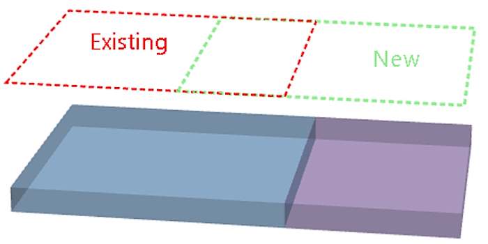
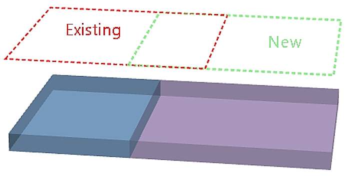
Overlaps |
Defines how the software handles overlapping areas.
If using a trim option, and the overlap portion entirely divides the activity areas, a new activity area is created in one of the divided areas. |
|
Pit |
Defines which pit from the material flow diagram the activity area will be assigned to. The activity area will be confined to the pit’s pit limit. Additionally, the activity area’s reserves and scheduled quantities will contribute to the pit’s totals. |
|
Mining Level |
Assigns the activity area to a mining level, which controls the depth of the activity area. When drawing an activity area, you define its XY extents by drawing a polygon. To make it a solid with depth, the software projects the polygon from the topography to the specified mining level.
For information about deriving an activity area solid, refer to Forming a solid. You can change the mining level assignment later. |
|
Activity |
Assigns the activity area to an activity type (for example, Mining, Drilling, Charging). The activity determines:
You can change the activity assignment later if needed. |
|
Resource |
Assigns the activity area to a resource (such as a shovel or drill). When you create the area, it’s added to the selected resource’s task list and appears in the Gantt chart. Resource assignment affects:
You can change the resource assignment later, including assigning multiple resources. |
3. Draw the activity area polygon
In the 3D scene, you create an activity area by drawing a polygon.
The software will extrude the polygon to form the activity area solid. The polygon must be drawn on the topography and within the assigned pit limit.
Prepare the plot view
Switch to plan view for the most accurate drawing. Your cursor will snap to the Z point on the topography at the selected XY location.
-
Click Down
 to enter plan view.
 -
Set the camera to Orthographic (Graphics Settings
 > 3D Settings > Camera Projection).
Use the Scene Manager to
-
Show only relevant objects, such as topography, feature layers, bucket positions (for example, enable feature layers or grade control shapes as visual guides for drawing accurate boundaries).
-
Hide other activity areas that might obscure your view.
Adjust the transparency for objects like the topography to better see depth and underlying features (in Client, go to the object’s respective tab to adjust its opacity).
Changing differing view items and transparencies
Draw polygon
Click points on the topography to define the polygon vertices. Each point uses the XY location you click and snaps to the Z value of the topography.
-
As you add points, the software previews the polygon (auto-closing the shape).
-
Rotate or zoom the camera as needed for accuracy.
-
Double-click to close the polygon and finish the drawing. Use Backspace to remove the last point or Esc to cancel.
Quick Estimates panel
While drawing, the Quick Estimate panel displays real-time metrics:
-
Mining level: The selected level for the area.
-
Average thickness: Vertical distance between the topography and mining level.
-
Plan area: Horizontal footprint of the polygon.
-
Volume: Estimated volume based on plan area and thickness.
These estimates help validate the size and depth before committing. Final values update after reserving.
4. Set mining direction
After you finish drawing the polygon, define the mining direction. This determines the order in which the resource works through the activity area during scheduling and animation.
-
The mining direction runs along the centre of the polygon, from a start point to an end point.
-
During scheduling, the area is mined in horizontal slices, progressing along this direction.
How to set the direction
A direction arrow appears on the polygon:
-
Green triangle = start point.
-
Red square = end point.
Drag either end of the arrow to rotate it. The arrow stays centred on the polygon while you adjust its angle.
When you’re satisfied with the direction, click anywhere outside the polygon to confirm. The software then creates the activity area solid.
Align the direction with the actual mining approach on site (e.g., toward the ramp or away from a wall).
Use plan view for precise alignment, then rotate the scene to check orientation.
If you need to change the direction later, use the Edit mining direction option from the right-click menu.
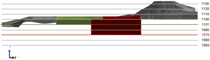
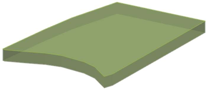
5. Forming the activity area solid
After you confirm the mining direction, XECUTE automatically creates the activity area solid. This process converts your 2D polygon into a 3D volume by projecting it from the topography down to the selected mining level.
During this step:
-
The polygon is extruded vertically to form a solid.
-
The solid is trimmed to respect:
-
Topography (roof of the area).
-
Pit limits (boundary constraints).
-
Overlapping areas that move material or share the same activity type.
-
-
The software evaluates reserves and updates the Reserve status to Evaluated when complete.
If issues occur:
-
XECUTE will display an error if the solid cannot be formed (for example, if the polygon crosses invalid geometry or the mining level is missing).
-
Common causes:
-
Polygon extends outside the pit limit.
-
Mining level not defined or incorrectly assigned.
-
Overlap conflicts with locked areas.
-
-
To resolve, adjust the polygon (refer to Editing activity areas below) or activity area properties (such as its assigned mining level)
For information about forming a solid and troubleshooting steps, refer to Forming a solid.
6. Validate the activity area solid
After the solid is created, review it in the 3D scene to confirm it reflects the intended shape and constraints (topography, pit limits, and overlaps). Validation ensures the area is schedulable and reserves are calculated correctly.
Change the display style
On the Activity Areas tab, use the Display Style property to switch between visualisation modes:
|
Display style |
Description |
|---|---|
|
Polygon
|
Shows the original design polygon before it’s fully processed. Useful for checking the drawn outline, but does not account for trimming by topography or pit limits. |
|
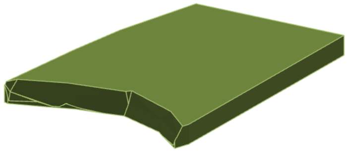
Solid
|
Displays the full 3D solid, projected from the mining level to the topography and trimmed by constraints. Best for validating the true shape. |
|
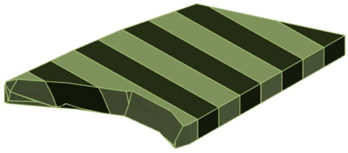
Slice
|
Shows the solid divided into slices (based on the Number of Slices property). Each slice is aligned perpendicular to the mining direction and represents how the area will be mined over time. |
|
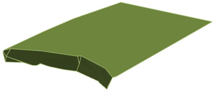
Roof
|
Displays only the top surface of the solid. |
|
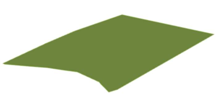
Floor
|
Displays only the bottom surface of the solid. |
On the Activity Areas tab, you can enable Wireframe mode with any display style to show only the outline, making it easier to see underlying geology or adjacent areas.
Use Solid or Slice view to confirm the final geometry, as these reflect all trimming rules (topography, pit limits, overlaps).
If the shape is incorrect, you can:
-
Edit the polygon (move or add vertices).
-
Change the mining level or activity type.
-
Redraw the area if necessary.